Archive for the ‘Uncategorized’ Category


ImageThis is my final completed project, mounted on some perspex with little feet to stay off the ground, and both boards held firmly in place so there not going anywhere!

Overall im very happy with how this turned out, I do feel that my PCB could be a bit smaller, but thats a thing I can improve on for my next project and will definitely try to improve my PCB artwork skills! I am a bit annoyed that I didnt get the humidity sensor working, but these things happen, ill know next time! Time in the last week was really flying by and at times I didnt think I was going to get it finished, it all came together in the end and I couldnt be happier about getting it finished, thanks to Ray for the help throughout the year too.

Hope you enjoyed the blog and seeing how this went week to week, because  I know I did!


This is by far the most important week of the whole entire project.

Now that the hardware was tested and correct, it was time to get the head down and stuck into the software side of the project and get these components hooked up to the LCD board and start printing some values 😀 

First case was the welcome message, second was the temp value, third was humidity values (ill talk about that in a second) and last but not least the Lux value 🙂

I put a command in the temperature function which you will see below, that if the temperature reached over 29 degrees celcius the fan would turn on and the LED would light, this would cool down my greenhouse and the light would be a warning light! By holding my finger on the thermistor I was able to increase the temperature and turn the LED and fan on and you could see the temperature rise on the LCD screen, and when you let go it would go back down to room temp.

On the light value case, if I put my finger on the sensor I would see a drop in lux value which was correct.

I did not get to program the humidity sensor in time as I prioritised the temperature sensor and the light sensor as I knew both of these were working better than the humidity sensor.

Below you can see my final code, with comments.

Project wiring code

Image

Image

Image

Probably one of the most important weeks of the project, the Sensor Control Board bench test, continuity and power tests!

I was absolutely nervous as hell doing this, although its straight forward its the results that scared me!! 😦 Any problems that I find now, are my own fault and no one elses..

I connected the required 5V to the PCB, no loud bangs or pops, so good so far.

Thermistor

To test the thermistor I connected the multimeter to the corresponding legs of the component and set it to the volt meter setting, I then put my finger over it to heat it up and expected to see a change in the voltage, which I did. Yesss!!

Light Sensor

I first made sure it was connected the correct way instead of testing it loads of times and wondering what was wrong, I double and triple checked it was in the correct way. Again, I connected the volt meter to the two legs of the component, but because it was flush with the board I didnt have any way to clip it to it so I had to get one of my class mates to put his finger over the diode, and when he did there was a change in the voltage which was exactly what I was looking for! Another one down, two to go!

Humidity Sensor

Another one to test, I connected both legs to the voltmeter and wet my finger off my soldering sponge, put it over the humidity sensor and seen a very very slow and small change in the voltage, although I wasnt entirely happy with it, Ray did warn us that this one may act up on us and not to waste too much time troubleshooting it, I didnt have the time anyways, time was ticking!

Fan And Led

To try turn these 2 components on, I had to connect 5v directly to the resistor before the Fan And LED, and after the transistor (BC337). The LED and fan had turned on, I was shocked, couldnt believe that the whole thing worked in the first go!!

I had printed out the required testing sheets to keep record of the acquired voltages and continuity checks, this will be included in my project report at the end of term.

Now its time to focus on the part of the project that was absolutely vital to get working first time. So after the obvious soldering all components in etc, paying very careful attention to which way the components went in place, which were polarised and which were not polarised by looking at the datasheets on moodle that were given to us. Also had to pay attention to the photodiode which was reverse biased as this could cause problems down the line.

The photodiode is very small with tiny legs making it hard to distuingish where the anode and cathode is, to the datasheet folder!!

After some, well a lot of time spent trying to trawl through the datasheet I found out that the cathode end is the one with the little piece sticking out of the side of the leg, and I had to stick the cathode end into the positive terminal on the circuit as its reverse biased. Below is the datasheet where I figured out where the cathode is.

Photodiode

Image


And below is my complete sensor and control board!!

Sensor Control Finished PCB

Image

Now I know that the LCD board works (except for the half lit LED haha) , I can move on to test whether the actual LCD screen itself works and displays messages the way I want. Using the arduino software along with my Arduino UNO, I began to write my first piece of wiring language, here goes nothing!

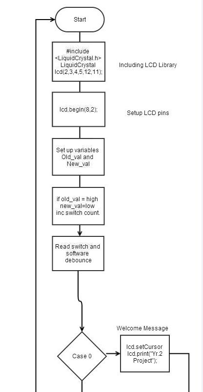
I knew exactly what I needed to do because of my switch menu algorithm, this actually came in handy even tho I moaned a lot about it haha! Id start off with my Welcome Message, then onto my  Temperature value, humidity value, and light value all being displayed on screen one after another by the press of the mode select button on the actual board.

Arduino Code

// include the library code:
#include <LiquidCrystal.h>
#include <math.h>
LiquidCrystal lcd(12,11,5,4,3,2);

// *** Variable decalarations ***

const int switchPin = 8;
int sw_state = 0; //new value of the mode switch
int no_of_switch_presses =0; //number of presses of the mode switch
int val;// store val of mode switch
int old_val=0; //store the previous value of valof the mode switch
int FAN=6;//declaring fan pin
int ledon=13;//declarin led pin
float TC;//making TC a global variable so it can be read from the function
float LuxVal;//making the Lux Value a global variable so it can be read from the function

void setup()
{
pinMode(switchPin,INPUT); // Set as input for the mode switch
pinMode(ledon,HIGH);//putting the LED on the LCD board constantly on
lcd.begin(8,2);//setting the cursor for the LCD screen
}

void loop(){
// **** Mode Select ****

val = digitalRead(switchPin); // Read the mode switch
if ((val == LOW) && (old_val ==HIGH)) {
no_of_switch_presses = no_of_switch_presses +1;
//Update the number of switch presses and inplement soft switch debounce
delay(50); // 50ms debounce delay
}
old_val = val; //val is now old so store it

digitalWrite(ledon,HIGH);

// Display whichever dipslay mode has been selected
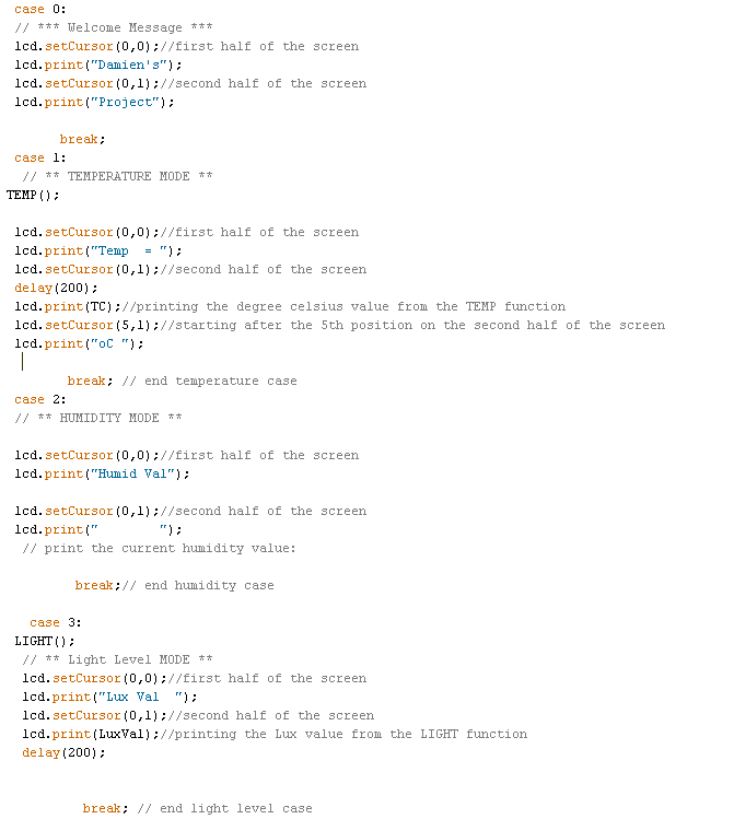
switch (no_of_switch_presses) {
case 0:
// *** Welcome Message ***

lcd.setCursor(0,0);//first half of the screen
lcd.print(“Damien’s”);

lcd.setCursor(0,1);//second half of the screen
lcd.print(“Project”);


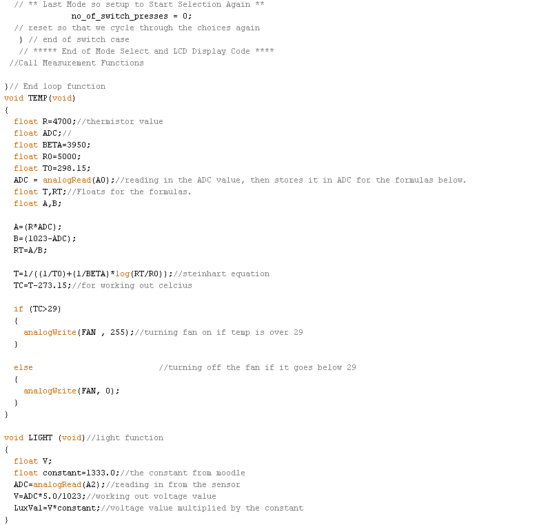
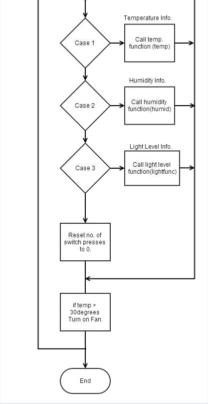
// ** TEMPERATURE MODE **
TEMP();

lcd.setCursor(0,0);//first half of the screen
lcd.print(“Temp = “);
lcd.setCursor(0,1);//second half of the screen
delay(200);
lcd.print(TC);//printing the degree celsius value which is going to be called TC.
lcd.setCursor(5,1);//starting after the 5th position on the second half of the screen
lcd.print(“oC “); //degrees celsius

break; // end temperature case

// ** HUMIDITY MODE **
lcd.setCursor(0,0);//first half of the screen
lcd.print(“Humid Val”);

lcd.setCursor(0,1);//second half of the screen
lcd.print(” “);
// print the current humidity value:

break;// end humidity case

LIGHT();
// ** Light Level MODE **
lcd.setCursor(0,0);//first half of the screen
lcd.print(“Lux Val “);
lcd.setCursor(0,1);//second half of the screen
lcd.print(LuxVal);//printing the Lux value from the LIGHT function
delay(200);

break; // end light level case

This was one of the more simple weeks, because the LCD board had been given to us we knew there was no problems in the design of the board and the only problems we could run into is if I place a component in the wrong place, which did happen… 😦

I knew I was going to be using the multimeter as a continuity tester in a few weeks so I played around with it a bit on the LCD board just to get the feel for it, and knowing where had to be tested when looking at the PCB layout on the computer too. 

There was a few tests that we had to conduct but it was done easily enough. I had to do a continuity test to ensure that theres no fault in the track between two components, allowing current to flow down and complete the circuit. The power test is to ensure that im getting the correct voltages in the correct places, like IC sockets etc, although there was none on this board.

I did run into one problem, I put a 10k resistor in before the LED which caused it to light up, but very very low amount of light was coming from it, although you could just about see it which was good. I read the resistor backwards because these were 5 band resistors which provide greater accuracy whereas im used to using 3 band resistors.

This is the week where we started actually making our own PCB boards, if theres any faults with the board now, its our own fault as its our own design.. We didnt have to worry about the LCD board not working, as that was given to us so we knew it worked, I suppose I had to trust Ray on this one 😀

The Manufacture of the sensor and control board involved a number of steps. First of all, I had to print the artwork that would be put onto some one sided fibreglass PCB board, peeled the protective layer off the PCB, and then put it in the sealed UV light machine to print the artwork onto the physical board. When this was done, the board was then put into a number of tanks.

Tank 1:

Developing – this tank removes the UV sensitive chemicals from the board. This will leave something like a stencil on the board thats in the shape of my original design.

Tank 2:

Etching – This tank removes the copper wherever the ‘stencil’ isint protecting it. After this process is done, we can now see all the different electrical connections that make the circuit.

Tank 3:

Photoresist Stripping – The photo resist is now removed off the copper tracks that are on the board.

Tank 4:

Tinning – Because copper tracks are now visible, a protective layer has to be put on the copper tracks otherwise they would oxidise, making them unusable.

Board in process of being manufactured

Image


Next was assembly of the boards, placing the components and soldering them into the correct spot for them. Because this was such a time consuming thing to do, it took both weeks 4 and 5 to do, but I didnt mind because I wanted it to work correctly the first time so did not want to rush it.

Week 6 – Algorithms!

Posted: March 8, 2014 in Uncategorized

Lets be honest, nobody likes algorithms, right??

This week I had to make 2 algorithms.

  • LCD Switch Menu algorithm
  • Temperature reading algorithm

The LCD Switch Menu one was easy enough and very straight forward, but the temperature reading ones were a bit more difficult.

My two algorithms are displayed below:

LCD Switch Menu Algorithm

Image

Image

Because the algorithm was so long, I snipped it in half and zoomed in on each so its easier to read.

Temperature reading Algorithm

Image

Week 3 – PCB Artwork Design

Posted: February 21, 2014 in Uncategorized

Now that I had the schematics drawn up, it was time to transfer it to PCB Artwork.

Although we were given LCD Screen Arduino Shield, we still had to design the PCB as we had to know the understanding of how it worked. We designed and made our own Sensor Control boards.

LCD Shield PCB Artwork

Image

Sensor and Control Board Artwork

Image

Week 2 – Schematic Designs

Posted: February 14, 2014 in Uncategorized

For this week we had to complete the schematic designs for both the LCD Board and the sensor control board.

Heres the schematic design for the LCD board that we had to recreate.

LCD Schematic

Image


The second schematic we had to complete was for the Sensor and Control Board.

Sensor Control Board Schematic

Image


As you can see, in the fan control section of the board we had to work out the value of R1. The resistor was connected to one of the ports on the 15 pin connection and then through a transistor (BC337). 

First step was to find the current of the fan using the formula I=P/V

  • P=1.23W
  • V=5V
  • I=246mA

Then looking at the data sheet for the BC337, we were able to find out the beta value, which was 400. With this, I was able to work out the base current. IB=IC/Beta 

  • IC=246mA (from above equation)
  • Beta=400 (from data sheet)
  • IB=615 microA

The final voltage is 4.3, because of the 0.707V voltage drop from the BC337. Now we can work out R.

R=V/I

  • V=4.3
  • I=615 microA
  • R=6.99 kOhms