For this week we had to complete the schematic designs for both the LCD Board and the sensor control board.
Heres the schematic design for the LCD board that we had to recreate.
LCD Schematic

The second schematic we had to complete was for the Sensor and Control Board.
Sensor Control Board Schematic
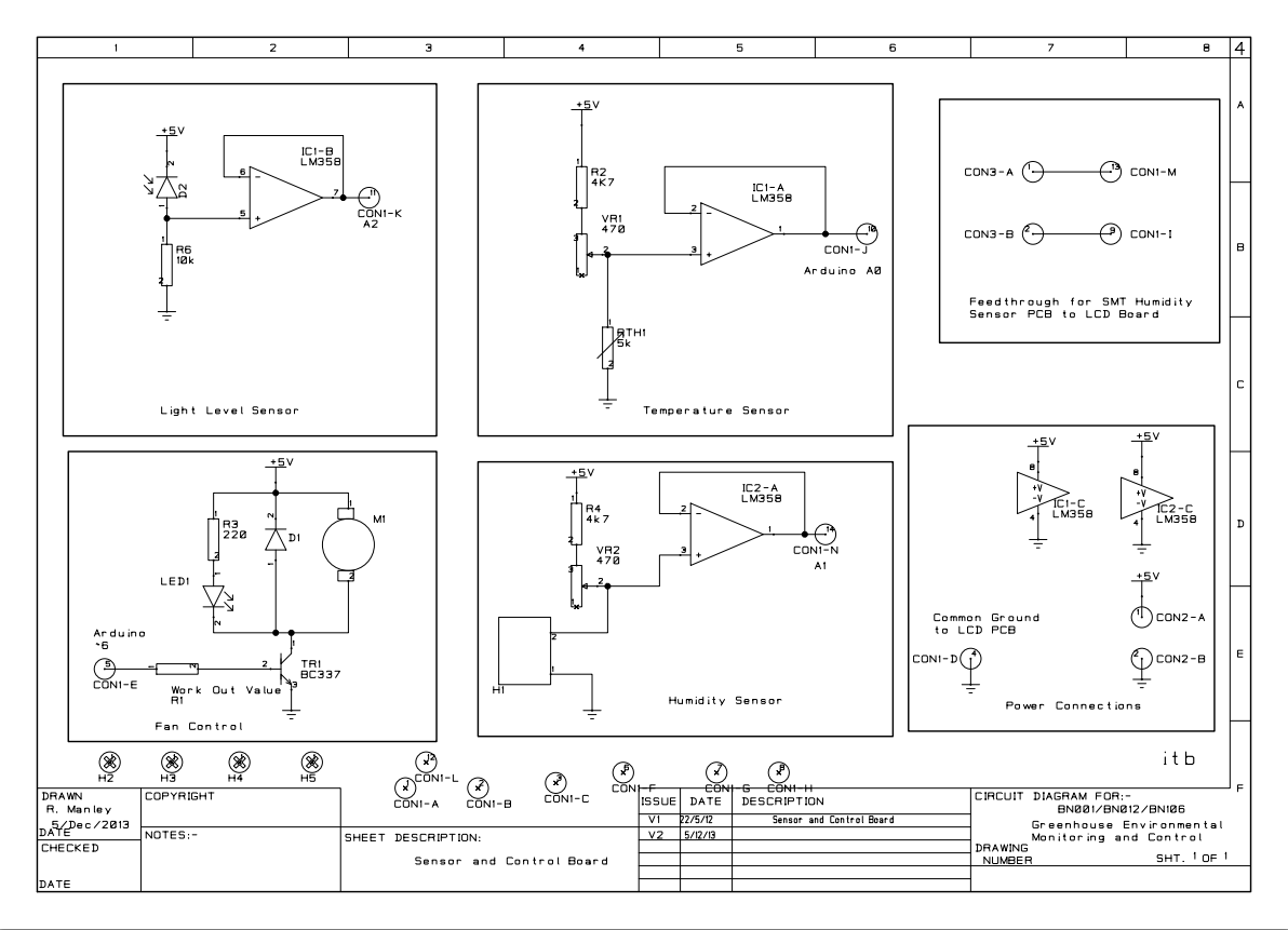
As you can see, in the fan control section of the board we had to work out the value of R1. The resistor was connected to one of the ports on the 15 pin connection and then through a transistor (BC337).
First step was to find the current of the fan using the formula I=P/V
- P=1.23W
- V=5V
- I=246mA
Then looking at the data sheet for the BC337, we were able to find out the beta value, which was 400. With this, I was able to work out the base current. IB=IC/Beta
- IC=246mA (from above equation)
- Beta=400 (from data sheet)
- IB=615 microA
The final voltage is 4.3, because of the 0.707V voltage drop from the BC337. Now we can work out R.
R=V/I
- V=4.3
- I=615 microA
- R=6.99 kOhms
